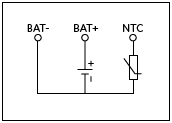
In lithium batteries, a thermistor with a negative temperature coefficient (NTC) is usually installed. The NTC thermistor can prevent the battery from being charged at too high or too low temperatures. Therefore, the battery has three connection terminals: the positive terminal (BAT+), the negative terminal (BAT-) and the connection terminal of the NTC thermistor (see Figure 1). Please note that some batteries with three connections only have ordinary resistors inside for identification. The value of the ordinary resistance will be constant and will not change with the battery temperature.
When using NTC thermistor, it should be connected between THM pin and ground (connected via BAT). A resistor (R7) is also connected between the THM pin and the reference voltage (VL), which creates a voltage divider. Choose the value of the resistor so that it has the same value as the NTC thermistor at a temperature of +25°C. The voltage on the THM pin at +25°C is equal to 0.5 VL. When the temperature rises or falls, the resistance of the NTC thermistor also falls or rises, and the voltage on the THM pin also falls or rises. The device will only charge when this voltage is between 0.28 VL and 0.74 VL. For contemporary NTC thermistors, this corresponds to a temperature between 0°C and 50°C. If there is no NTC thermistor available, R8 should be added, which will result in a voltage of 0.5 VL on the THM pin.