The concept of temperature
From a physical point of view, heat is a measure of the energy contained in the body due to the irregular movement of its molecules or atoms. Just as tennis balls have more energy with increasing speed, the internal energy of the body or gas increases as the temperature increases. Temperature is a variable that, along with other parameters such as mass and specific heat, describes the energy content of the body.
The basic measure of temperature is Kelvin degree. At 0 ° K (Elvin), every molecule in the body is at rest and there is no more heat. Therefore, there is no possibility of negative temperature because there is no state of lower energy.
In daily use, the usual practice is to use centigrade (formerly centigrade). Its zero point is at the freezing point of water, which can be easily reproduced in practice. Now 0 ° C is by no means the lowest temperature, because everyone knows from experience. By extending the centigrade scale to the lowest temperature at which all molecular motion stops, we reach – 273.15 degrees.
Man has the ability to measure temperature through his senses in a limited range. However, he was unable to accurately reproduce quantitative measurements. The first form of quantitative temperature measurement was developed in Florence in the early 17th century and relied on the expansion of alcohol. Scaling is based on the highest temperatures in summer and winter. A hundred years later, the Swedish astronomer Celsius replaced it with the melting and boiling points of water. This gives the thermometer the opportunity to zoom in and out at any time and reproduce the readings later.
Electrical measurement temperature
Temperature measurement is important in many applications, such as building control, food processing, and the manufacture of steel and petrochemical products. These very different applications require temperature sensors with different physical structures and usually different technologies
In industrial and commercial applications, measurement points are usually far away from indication or control points. Further processing of measurements is usually required in controllers, recorders or computers. These applications are not suitable for direct indication of thermometers because we know them from everyday use, but need to convert the temperature into another form of device, the electrical signal. In order to provide this remote electrical signal, RTD is usually used. Thermistors and thermocouples.
RTD adopts the characteristic of metal resistance changing with temperature. They are positive temperature coefficient (PTC) sensors whose resistance increases with temperature. The main metals used are platinum and nickel. The most widely used sensors are 100 ohm or 1000 ohm RTDS or platinum resistance thermometers.
RTD is the most accurate sensor for industrial applications and also provides the best long-term stability. The representative value of platinum resistance accuracy is + 0.5% of the measured temperature. After one year, there may be + 0.05 ° C change through aging. Platinum resistance thermometers have a temperature range of – 200 to 800 ° C.
Change of resistance with temperature
The conductivity of a metal depends on the mobility of the conducting electrons. If a voltage is applied to the end of the wire, the electrons move to the positive pole. Defects in the lattice interfere with this motion. They include external or missing lattice atoms, atoms at grain boundaries and between lattice positions. Since these fault locations are temperature independent, they produce a constant resistance. With the increase of temperature, the atoms in the metal lattice exhibit increased oscillations near their stationary positions, thus hindering the movement of the conducting electrons. Since the oscillation increases linearly with temperature, the resistance increase caused by the oscillation depends directly on the temperature.
Platinum has been widely accepted in industrial measurement. Its advantages include chemical stability, relatively easy fabrication (especially for wire manufacturing), the possibility of obtaining it in high purity form, and reproducible electrical properties. These characteristics make platinum resistance sensor the most widely interchangeable temperature sensor.
Thermistors are made of some metal oxides and their resistance decreases with increasing temperature. Because the resistance characteristic decreases with the increase of temperature, it is called negative temperature coefficient (NTC) sensor.
Due to the nature of the basic process, the number of conducting electrons increases exponentially with temperature; therefore, the characteristic shows a strong increase. This obvious nonlinearity is a disadvantage of NTC resistors and limits its effective temperature range to about 100 ° C. They can, of course, be linearized by automated computers. However, the accuracy and linearity can not meet the requirements of large measurement span. Their drift at alternating temperatures is also larger than that of RTD. Their use is limited to monitoring and indicating applications where the temperature does not exceed 200 ° C. In this simple application, they are actually superior to the more expensive thermocouples and RTDs, considering their low cost and the relatively simple electronic circuits required.
The basis of thermocouple is the connection between two different metals, thermistor. The voltage generated by thermocouple and RTD increases with temperature. Compared with resistance thermometers, they have a higher upper temperature limit, with a significant advantage of several thousand degrees Celsius. Their long-term stability is slightly poor (several degrees after a year), and the measurement accuracy is slightly poor (average + 0.75% of the measurement range). They are often used in ovens, furnaces, flue gas measurement and other areas where temperatures are higher than 250 ° C.
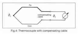
Thermoelectric effect
When two metals are connected together, thermoelectric voltage is produced due to the different binding energy of electrons and metal ions. The voltage depends on the metal itself and the temperature. In order for this thermal voltage to generate current, the two metals must of course be connected together at the other end to form a closed circuit. In this way, a thermal voltage is generated at the second junction. The thermoelectric effect was discovered by Seebeck in 1822. As early as 1828, Becquerel suggested the use of platinum palladium thermocouple for temperature measurement.
If there is the same temperature at both junctions, there is no current flow because the partial pressures generated at the two points cancel each other out. When the temperature at the junction is different, the voltage generated is different and the current flows. Therefore, thermocouple can only measure temperature difference.
The measuring point is a junction exposed to the measured temperature. The reference junction is a junction at a known temperature. Since the known temperature is usually lower than the measured temperature, the reference junction is usually called a cold junction. In order to calculate the actual temperature of the measuring point, the cold end temperature must be known.
Older instruments use thermostatic control junction boxes to control the cold junction temperature at known values such as 50c. Modern instruments use thin-film RTD at the cold end to determine its temperature and calculate the temperature of the measuring point.
The voltage produced by the thermoelectric effect is very small and is only a few microvolts per degree centigrade. Therefore, thermocouples are not normally used in the range of – 30 to + 50 ° C, because the difference between the reference junction temperature and the reference junction temperature is too small to produce a non-interference signal.
RTD wiring
In a resistance thermometer, the resistance varies with temperature. To evaluate the output signal, a constant current passes through it and the voltage drop across it is measured. For this voltage drop, Ohm’s law is obeyed, v = IR.
The measurement current should be as small as possible to avoid sensor heating. It can be considered that the measurement current of 1mA will not introduce any obvious error. The current produces a voltage drop of 0.1V in PT 100 at 0 ℃. This signal voltage must now be transmitted through the connecting cable to the indication point or evaluation point with minimal modification. There are four different types of connection circuits:
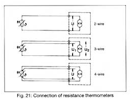
2-wire circuit
A 2-core cable is used for the connection between the thermometer and the evaluation electronics. Like any other electrical conductor, the cable has a resistance in series with a resistance thermometer. As a result, the two resistors are added together and the electronics interpret it as a temperature rise. For longer distances, the line resistance can reach several ohms and produce a significant offset in the measured value.
3-wire circuit
In order to minimize the influence of line resistance and its fluctuation with temperature, a three wire circuit is usually used. It includes running additional wires on one of the contacts of the RTD. This results in two measurement circuits, one of which is used as a reference. The 3-wire circuit can compensate the line resistance in terms of its number and temperature variation. However, all three conductors are required to have the same characteristics and to be exposed to the same temperature. This is usually applied to a sufficient extent to make 3-wire circuits the most widely used method today. No line balancing is required.
4-wire circuit
The best connection form of resistance thermometer is 4-wire circuit. Measurement depends neither on line resistance nor on temperature induced changes. No line balancing is required. The thermometer provides measurement current through a power connection. The voltage drop on the measuring line is picked up by the measuring line. If the input resistance of an electronic device is many times greater than the line resistance, the latter can be ignored. The voltage drop determined in this way is independent of the characteristics of the connecting wire. This technique is usually used only for scientific instruments that require a measurement accuracy of one hundredth.
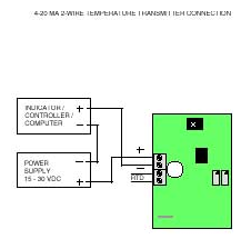
2-wire transmitter
By using a 2-wire transmitter instead of a multi wire cable, the problem of a 2-wire circuit as described above can be avoided. The transmitter converts the sensor signal into a normalized current signal of 4-20mA, which is proportional to the temperature. The power supply to the transmitter also operates through the same two connections, using a basic current of 4 mA. The 2-wire transmitter provides an additional advantage, that is, signal amplification greatly reduces the impact of external interference. There are two arrangements for positioning the transmitter. Since the distance between non amplified signals should be as short as possible, the amplifier can be directly installed on the thermometer in its terminal head. This best solution is sometimes not possible due to structural reasons or considerations that the transmitter may be difficult to reach in the event of a failure. In this case, the rail mounted transmitter is installed in the control cabinet. The advantage of improved access is that it is purchased at the cost of a longer distance that the non amplified signal must travel.
Thermistor wiring
The resistance of a thermistor is usually several orders of magnitude greater than that of any lead wire. Therefore, the effect of lead resistance on temperature readings is negligible, while thermistors are almost always connected in a 2-wire configuration.
Thermocouple wiring
Unlike RTDS and thermistors, thermocouples have positive and negative legs, so polarity must be observed. They can be connected directly to the local 2-wire transmitter and the copper wire can be returned to the receiving instrument. If the receiving instrument can accept thermocouple input directly, the same thermocouple wire or thermocouple extension wire must be used all the way back to the receiving instrument.